BENEFITS
Quick and easy setup using HSE’s Insight software enables the following independent programmable parameters for each sensor to be logged:
- ID number
- Multiplier and offset
- Sample interval
- Amount of change needed to generate an analog event
- Transmission hold-off time
- Amount of change needed to override transmission hold-off time
- A timed report interval and a logging interval
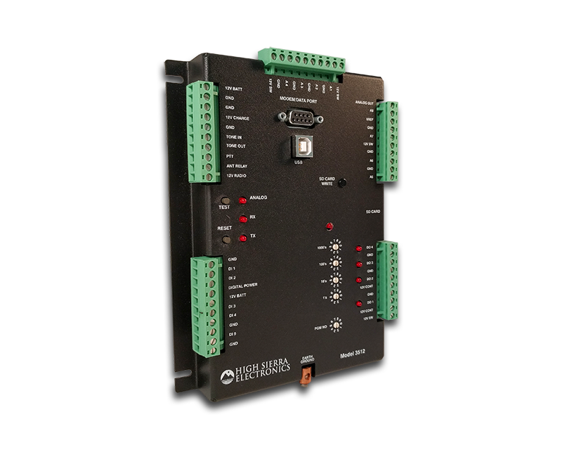
The Hydromet Data Logger & Controller – Model 3512-00 is a powerful and flexible addition to the 3306 family of transmitter products designed with the field technician in mind. It can be used as a simple data logger and in more complex control systems such as the 3580 Series controllers. The Model 3512 accepts up to 8 Analog (plus internal battery), up to 2 shaft encoders, up to 2 precipitation, SDI-12, wind speed, wind direction, and peak gust.
Additional Hydromet Data Logger & Controller features include fuse protection on the solar power input, battery and 12V switched to avoid damage to the unit through shorting (these fuses automatically reset when they cool off); and a dedicated USB port for programming, data retrieval, and uploading of new firmware versions.
You can use the included Insight software for fast, easy set-up of the Model 3512 from either a desktop or laptop computer in the field. The 3512 internal firmware is upgradable in the field. New firmware versions can be downloaded via the USB cable in just a few seconds.
The Hydromet Data Logger & Controller is housed in an aluminum enclosure and connections are made using plug-in terminal strips which allow quick disconnect for easy installation or replacement. The Hydromet Data Logger & Controller is typically mounted in a gauge house, weather resistant cabinet, or NEMA 4 enclosure to protect it from the elements. The on-board ALERT modem can be used with VHF or UHF data radios for data transmission, however, the Hydromet Data Logger & Controller also works with other communication devices such as GPRS radios or CDMA (cellular transmitters) using its serial port.
Hydromet Data Logger
You can program the following parameters independently for each sensor to be logged by the Hydromet Data Logger & Controller: ID number, multiplier and offset, sample interval, amount of change needed to generate an analog event, transmission hold-off time, amount of change needed to override transmission hold-off time, a timed report interval, and a logging interval.
Hydromet Data Logger & Controller data is logged on a Secured Data (SD) memory card and can be retrieved via the USB or serial port. The SD memory card can also be removed from the Hydromet Data Logger & Controller for later downloading and replaced with a spare card. The Hydromet Data Logger & Controller – Model 3512-00 is supplied with a 16 GB SD card.
Hydromet Controller
The Hydromet Data Logger & Controller includes certain controller functions that either, through commands sent remotely by someone monitoring transmitted data or commands generated autonomously from local sensor monitoring, activate outputs and/or issue commands to remotely located controllers to also activate their outputs. Applications for these controller functions, include automated public warning systems, irrigation gate control, pump management, etc. The most popular application, public warning systems, warn travelers of an imminent safety threat from flood, icy roads, high wind, low visibility, or some other measurable weather event and activate public warning devices such as flashing beacons, barrier gates, or sirens to improve traffic and public safety. Controller systems often include sensors other than the primary triggering sensor to gather extra information, such as a rain gauge on a water level monitoring system.
A typical use for the Hydromet Data Logger & Controller is at a location where water may cover a road at a low water crossing during storm events making travel along the road dangerous or impossible. These High Water Detection Systems (HWDS) have one or more Hydromet Data Logger & Controllers configured as Control Station with one or more water level sensors (often pressure transducers). These sensors are associated with one or more of 4 output channels, and through configurable high and low thresholds, activate the Hydromet Data Logger & Controller’s output channel when the pre-defined water level is exceeded. Through radio communications, the primary Hydromet Data Logger & Controller will send commands to remote controller stations, Advance Warning Stations (AWS), where the same output channel activates a public warning device. A confirmation message and retry sequence confirms activation and a summary message is sent back to the primary Hydromet Data Logger & Controller and Base Station, if set up.
The primary Hydromet Data Logger & Controller sends locally logged measurements and commands in timed reports, event generated reports, and command generated status reports, to a remote base station for off-site monitoring. The remote Hydromet Data Logger & Controllers send timed reports and command generated response reports to its primary controller and to the system’s Base Station. At each Hydromet Data Logger & Controller station, a deep cycle battery with a solar panel or an AC Charger will supply power for all the station functions.
Control functions can be programmed through the Insight software included with the Hydromet Data Logger & Controller.